
The risk of moisture penetration is greater if you have part of the construction embedded in the ground. For example, the problem is related to:
● underground parts of buildings,
● support layers in line structures,
● support layers in lot fencing.
For recessed buildings, rainwater runs down the terrain surface towards the wall. Due to this, in some places there is a risk of increased stress with pressurized water.
LITHOPLAST® SANA 15/0.8 or LITHOPLAST® INSTAL 20/1.0 drainage studded membrane should be used with the drainage via perforated piping.
The surface drainage made of a studded membrane creates the first barrier against water. In addition, it serves as a protection of the proper waterproof insulation against mechanical damage. Thanks to this the drainage foil significantly reduces the risk of water leakage into the house.
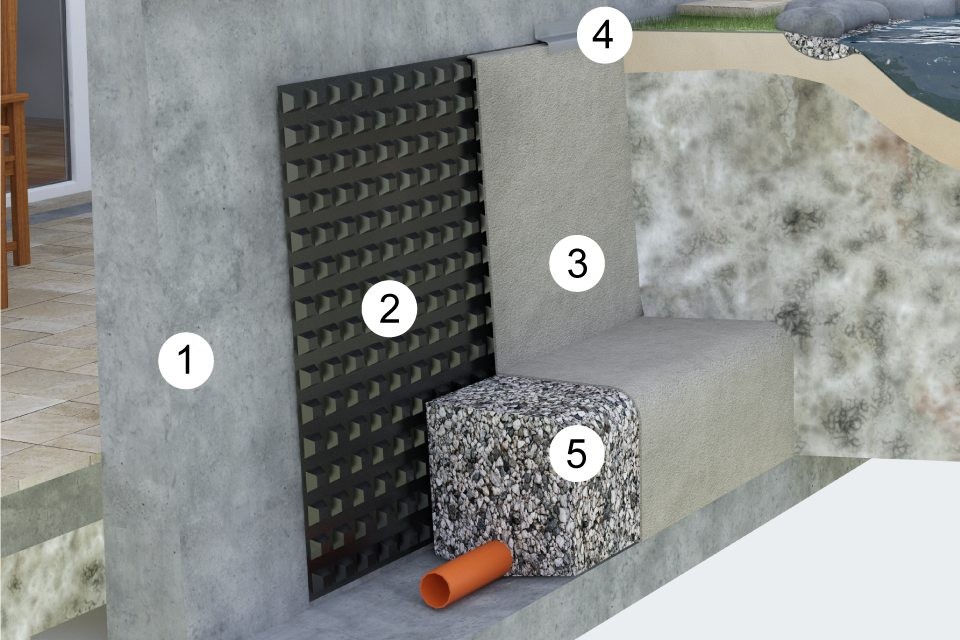
1. The first layer is a flat base without protrusions, excess mortar and concrete, or sharp edges that could damage the studded membrane.
2. Apply LITHOPLAST® SANA 15/0.8 or LITHOPLAST® INSTAL 20/1.0 drainage foil to a level surface and loosely unfold it along the wall. If the depth of the surface drainage does not exceed the width of studded membrane strip, place another strip horizontally along the building structure. If the drainage depth is higher than the foil width, run it vertically downwards and align it with one row profile overlap. We place a double-sided adhesive butyl rubber tape of 15 mm into the joint. The studs are oriented out of the wall and in combination with geotextile form a drainage gap for water outflow.
3. Then place the IZOLTECH H 500 filter geotextile. If you used the LITHOPLAST® INSTAL 20/1.0 studded membrane in the previous step, it is recommended to work with the PetexDren 400 twisted polyethylene mesh to increase the bearing capacity.
4. Anchoring of the membrane is performed at the highest point (150 mm above the planned ending at terrain level approx.). After setting the refilled excavated soil, cut the membrane at required height and perform ending with an eave board.
5. The gravel drainage block fr 16-32 with a perforated drainage tube DN 100 with outlet in sewerage is the last step to be done. Everything packed in filtering geotextile IZOLTECH S 500.